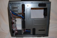
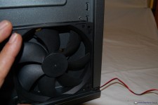
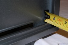
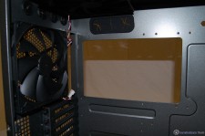
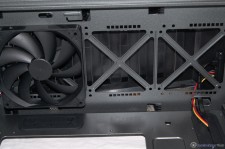
The interior tour begins with a look at the right side, behind the motherboard tray. There is a huge cutout area to access a CPU cooler’s mounting mechanism, which prevents having to remove the motherboard to change out a CPU cooler. You can also see from this view, the five well placed rubber grommet protected cable management holes. In addition to those five holes, there are two additional cable management holes, one just above where the PSU gets mounted, and another large square hole forward of the PSU mounting area. Remember the fan mounting option included on the right side panel? Well, I can tell you it fits between the panel and the motherboard tray just fine, or at least a 25 mm fan does. Once that fan is in place, it will be centered behind the CPU cooler access hole. With a tape measure, I come up with just a tad under 1 inch of clearance between the motherboard tray and the right side panel. This GRone case certainly does not lack for cable management options; that’s for sure!
 |
 |
 |
|
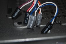
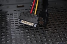
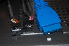
As we flip the case around to have a look at the inside, let’s begin by looking at the included wiring. The front panel switch connections are all present and accounted for, including a power LED lead that is double wired for both two pin and three pin applications. Additionally, there are the SATA power and data leads needed for the EZ-Swap, the USB 2.0 and USB 3.0 motherboard header cables, and the front panel audio connector cable.
 |
 |
 |
|
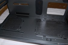
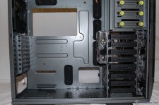
The interior is painted in the same metallic grey as the rest of the case, and being a full tower, has plenty of room inside. A full view of the interior again shows the abundance of cable management features built into the GRone. The GRone has the ability to accept CPU coolers up to 206 mm, a little over 8″. In addition to accepting the tallest of CPU air coolers, it can also accept four video cards up to 365.5 mm in length, just short of 14.5 inches. Hardly any worries about using any CPU cooler or video card!
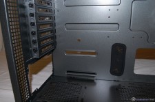
At the bottom PSU mounting area, we can see a top view of the filters and the support rails for the PSU to rest on. I usually like to see some sort of rubber on the PSU support rails to provide a certain level of anti-vibration. Moving upward along the rear of the GRone we can see the PSU opening, the eight ventilated PCI expansion slot covers, and the included 140 mm exhaust fan.
 |
 |
 |
|
As we move our way to the top panel area, we can see an additional included 140 mm fan installed. There is plenty of room here for either a 3X120 mm or 3X140 mm radiator, along with 25 mm thick fans. I came up with 2.5 inches or 63 mm between the top deck and the edge of the motherboard. You won’t get the thickest radiators available up there, but there are plenty of options that will fit just fine. If you do install a triple fan radiator up top, it will protrude into the uppermost 5.25 drive bay. But, that is not an issue, as that particular bay is not usable for a 5.25′ drive because of the front panel I/O in front of it.
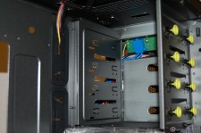
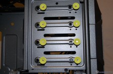
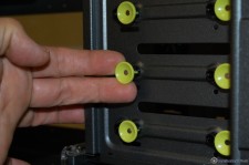
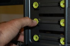
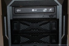
Moving over to the front area you can see what I mean about the uppermost 5.25″ drive bay being blocked by the front panel I/O controller. However, as advertised, there are still three more usable bays here. I suppose the uppermost bay could be used to house an additional HDD if you were to use a 5.25″ to 3.5″ adapter. Installing a drive in one of the 5.25″ bays couldn’t be any easier. You simply pull the yellow knobs outward, slide the drive in from the front of the case, and secure it by pushing the yellow knobs back in. There have been provisions made to further secure the drive with screws, if desired.
 |
 |
 |
 |
 |
|
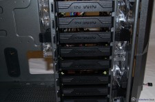
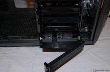
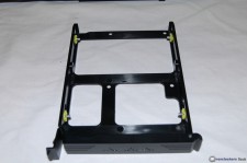
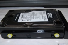
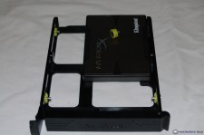
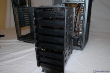
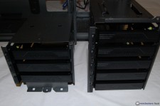
Continuing down the front side we come to the HDD cage area, which has a lot to discuss. There are eight slide out HDD trays that will accept both traditional 3.5″ HDDs and 2.5″ SSDs. The trays are pliable enough to allow you to simply place one side of a 3.5″ HDD in at an angle to engage two of the pins on one side of the tray. Then, lower the other side of the HDD and snap the other two pins in place. Simple, tool-less, secure, and works great!
 |
 |
 |
 |
 |
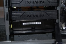 |
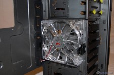
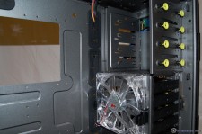
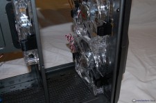
The HDD cage is made up of two pieces: the bottom holds three HDDs, and the top holds five. The complete assembly can be taken out by removing three screws. Once removed, we can see the three included LED fans that are arranged in a push/pull configuration across the HDD cage area. The two fans at the very front are wired into the controller at the front panel. The cages can be installed independently, so if you need room for water cooling pumps or reservoirs, the case can be set up to meet those needs. A 2X120 or 2X140 mm radiator can be installed along the bottom with the lower cage removed; and perhaps the same can be done along the front of the case with a little modification to the lower section of the 5.25″ drive bay housing. All in all, definitely a water cooling friendly case!
 |
 |
 |
 |
 |
|
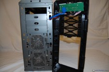
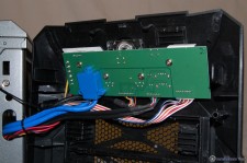
Finally, I went ahead and removed the front panel to have a look at the back side of the I/O controller. Everything is securely connected and the soldering points were well done; nothing to complain about here.
 |
 |

 Posted in


